Isometric: from Ancient Greek ἰσομέτρητος
(isométrētos, “equal in measure”), from ἴσος (ísos, “equal”) +
μέτρον (métron, “measure”).
There is a certain elegance to isometric
drawings.
What seems two-dimensional…
…can suggest something else.
And with a little shading…
…and turning…
…can look like the real thing.
And you can use that cube…
…to construct a cylinder.
And using a cylinder in a cube…
…rotated 90 degrees into each
cube face…
…gives you a sphere with the same
diameter as the cylinder.
_________________________________________________
And what is this elegant technique good
for? Let’s take a look.
In Joseph Gwilt's Civil Architecture, from 1825, we find a proportion study of Amien
Cathedral in isometric form. The view is perfect for comparing the three-dimensional modularity of the cathedral’s structure.
Auguste Choisy was a professor of
architecture at the École Nationale des Ponts et Chaussées, in Paris, from 1877
to 1901. He was an authority on ancient building systems, and wrote L'art de bâtir chez les byzantins and L'art
de bâtir chez les romans. The drawings above are from those two books, and are all examples of
isometric drawing. Note that Choisy has provided a scale for each axis, making
each drawing quite informative as well as beautiful. (I’d dearly like to get my
hands on copies of these books, but the timing isn’t right [I’m planning a
move] and they would be expensive.)
This isometric of a work room by Walter
Gropius (1923) is also highly informative and beautiful, but in a more
abstract way than Choisy’s drawings. The see-through walls and ceiling allow a
viewer to easily explore the design.
R. Buckminster Fuller’s 1927 collage
presentation of the Dymaxion House does a wonderful job of describing the
complex geometry of the design. Placing the isometric drawing between the plan
and the elevation makes the design easy to understand. However, I would hardly
call the drawing beautiful, and the repeated geometry gets old really fast.
This isometric of water wheel gears
from the book Windmills & Watermills
by J. Reynolds (1970) gives a wonderfully clear idea of the watermill setup.
It would take a number of plans, elevations and sections to give as much
information as this single isometric. And I, for one, think the drawing is
gorgeous.
This isometric of a redevelopment plan
for Rotebuhlplatz in Stuttgart, by Putz & Weber Architects, illustrates one
of the obvious uses for isometrics: simple aerial views. Both this and the
following two isometric studies are by Rob Krier; this aerial is from his book Urban Space (1979).
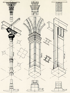
A sheet of isometrics illustrating column
types in Rob Krier’s Elements of
Architecture (1983). Surrounding the isometrics with scaled elevations and
plans makes this example visually informative and practically useful.
This sheet of rough isometric sketches
is also from Elements of Architecture.
In each case Krier juxtaposes the isometric with a simple plan. In spite of the
roughness of the drawings, I find the approach quite elegant.
Leon Krier is the younger brother of
Rob, and a well-known neo-traditional architect in his own right. The above
drawing of the School at St. Quentin in Yvelines, France, shows the simple
elegance and clarity of the isometric. It also shows the quirky style of
architecture practiced by the Kriers in the 70s and 80s.
In the early 80s Leon Krier worked on
the “New District of Tegel” in Berlin. The presentation drawings produced for
the proposal included many bird’s-eye and worm’s-eye axonometrics. The lower
drawing above is a simple projection drawing of a rectilinear grid of blocks,
an iconic example of the isometric. The drawing above it is a curious inverted
worm’s-eye view of a complex. In spite of its multiple grids and curves, I
would label it an isometric, since the main grid of columns is close to the
requisite 30-degree angle. In any case, it is a wonderful bit of frippery that
I loved when I first saw it years ago.
I have done quite a few isometrics in
my time. This aerial of the Franklin & Marshall College master plan by Kliment
Halsband Architects is perhaps the closest to a simple aerial. It was produced
by making a computer model of the campus; printing out a hidden wire-frame
view; and painting in the simple materials and modeling with airbrush. It would
have been as easy to make an aerial perspective, but the look of an isometric
was preferred by the client.
Just to summarize…
An isometric drawing takes a rectilinear
object and draws it as if seen from 45 degrees off each axis, but with no
foreshortening. Measurement along each axis is easy and accurate, but any other
measurement (say a diagonal across a cube’s face) needs a different scale. The
advantage, obviously, is being able to see the object in three dimensions while
still being able to measure the most important parts.
Finally, isometric drawing, unlike plan
or elevation projection, is easily done by computer modeling. My aerial drawing
for Franklin & Marshall College involved a model which could be viewed
either as a perspective or as a parallel projection. I simply turned off the
perspective control to create the isometric drawing.
Computer modeling opens an easy and
wide range of parallel projection views, but there are areas where hand drawing
is still king. The following posts on elevation projection and plan projection
drawing will explore two of them.


No comments:
Post a Comment